-
-
-
 
near IR surveys

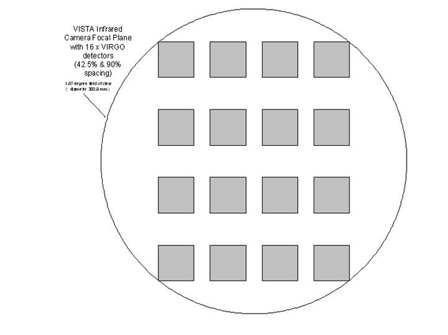
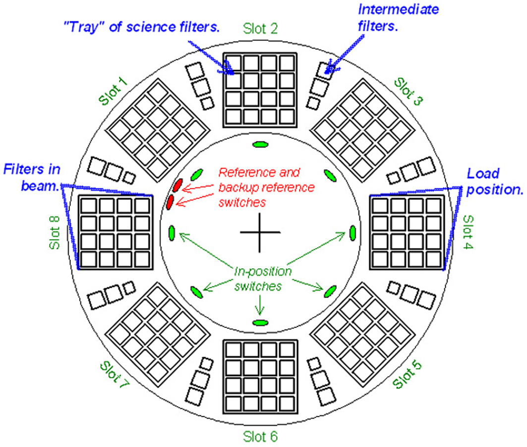
Images of VISTA Focal Plane

Click on the picture to download a high resolution version (opens in new window)

VISTA Focal Plane: 16 detectors on their mount
image: IMGP4190.jpg
Credit: VISTA

VISTA camera

VISTA Focal Plane: Geometry
image: geometry_300dpi.jpg
Credit: VISTA

Filter wheel

VISTA Focal Plane: Detector Layout.
Each of the 4 groups of (green) detectors in the Y direction (e.g. #s 1-4, 5-8, 9-12, 13-16) is read out by a separate IRACE controller (#1-4 each controlling 4 detectors A-D).
The blue areas are CCDs operating in the optical region (I band), two autoguiders (AG) and two low order wave front sensors (LOWFS). The two sets in the positive Y (PY) and negative Y (NY) sides of the focal plane cover sufficient area that a suitbale bright star to use should (almost) always be found with their field of view.
image: FocalPlane.gif
Credit: VISTA

VISTA camera

VISTA Focal Plane: Making a filled tile from 6 individual pawprint exposure on the sky. Each piece of sky away from theedges is covered twice.
image: Tile_w11p6cm_300dpi.gif
Credit: VISTA

Filter wheel

VISTA Focal Plane: Filter Wheel.
image: Filter_wheel_w9cm_300dpi.jpg
Credit: VISTA

Filter wheel

VISTA Focal Plane: Image Quality as function of radius .
image: encircled_energy_distribution_w9cm_300dpi.jpg
Credit: VISTA

VISTA camera


Menu of 23/10/2012
-   -
Page updated 17 January 2007 by J.P.Emerson to whom comments should be sent
[ESO][VISTA Home]